Content - VDE
Werbung
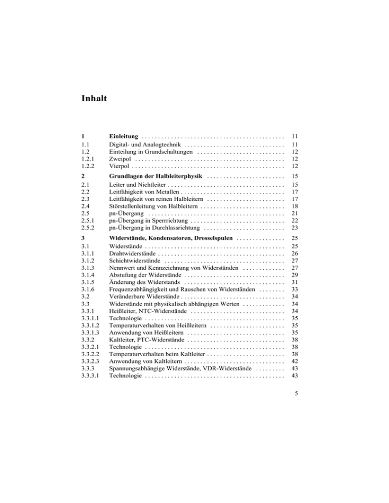
Inhalt 1 1.1 1.2 1.2.1 1.2.2 Einleitung . . . . . . . . . . . . . . . . . . . . . . . . . . . . . . . . . . . . . . . . . . . . Digital- und Analogtechnik . . . . . . . . . . . . . . . . . . . . . . . . . . . . . . . Einteilung in Grundschaltungen . . . . . . . . . . . . . . . . . . . . . . . . . . . Zweipol . . . . . . . . . . . . . . . . . . . . . . . . . . . . . . . . . . . . . . . . . . . . . . Vierpol . . . . . . . . . . . . . . . . . . . . . . . . . . . . . . . . . . . . . . . . . . . . . . . 11 11 12 12 12 2 2.1 2.2 2.3 2.4 2.5 2.5.1 2.5.2 Grundlagen der Halbleiterphysik . . . . . . . . . . . . . . . . . . . . . . . . Leiter und Nichtleiter . . . . . . . . . . . . . . . . . . . . . . . . . . . . . . . . . . . . Leitfähigkeit von Metallen . . . . . . . . . . . . . . . . . . . . . . . . . . . . . . . . Leitfähigkeit von reinen Halbleitern . . . . . . . . . . . . . . . . . . . . . . . . Störstellenleitung von Halbleitern . . . . . . . . . . . . . . . . . . . . . . . . . . pn-Übergang . . . . . . . . . . . . . . . . . . . . . . . . . . . . . . . . . . . . . . . . . . pn-Übergang in Sperrrichtung . . . . . . . . . . . . . . . . . . . . . . . . . . . . . pn-Übergang in Durchlassrichtung . . . . . . . . . . . . . . . . . . . . . . . . . 15 15 17 17 18 21 22 23 3 3.1 3.1.1 3.1.2 3.1.3 3.1.4 3.1.5 3.1.6 3.2 3.3 3.3.1 3.3.1.1 3.3.1.2 3.3.1.3 3.3.2 3.3.2.1 3.3.2.2 3.3.2.3 3.3.3 3.3.3.1 Widerstände, Kondensatoren, Drosselspulen . . . . . . . . . . . . . . . Widerstände . . . . . . . . . . . . . . . . . . . . . . . . . . . . . . . . . . . . . . . . . . . Drahtwiderstände . . . . . . . . . . . . . . . . . . . . . . . . . . . . . . . . . . . . . . . Schichtwiderstände . . . . . . . . . . . . . . . . . . . . . . . . . . . . . . . . . . . . . Nennwert und Kennzeichnung von Widerständen . . . . . . . . . . . . . Abstufung der Widerstände . . . . . . . . . . . . . . . . . . . . . . . . . . . . . . . Änderung des Widerstands . . . . . . . . . . . . . . . . . . . . . . . . . . . . . . . Frequenzabhängigkeit und Rauschen von Widerständen . . . . . . . . Veränderbare Widerstände . . . . . . . . . . . . . . . . . . . . . . . . . . . . . . . . Widerstände mit physikalisch abhängigen Werten . . . . . . . . . . . . . Heißleiter, NTC-Widerstände . . . . . . . . . . . . . . . . . . . . . . . . . . . . . Technologie . . . . . . . . . . . . . . . . . . . . . . . . . . . . . . . . . . . . . . . . . . . Temperaturverhalten von Heißleitern . . . . . . . . . . . . . . . . . . . . . . . Anwendung von Heißleitern . . . . . . . . . . . . . . . . . . . . . . . . . . . . . . Kaltleiter, PTC-Widerstände . . . . . . . . . . . . . . . . . . . . . . . . . . . . . . Technologie . . . . . . . . . . . . . . . . . . . . . . . . . . . . . . . . . . . . . . . . . . . Temperaturverhalten beim Kaltleiter . . . . . . . . . . . . . . . . . . . . . . . . Anwendung von Kaltleitern . . . . . . . . . . . . . . . . . . . . . . . . . . . . . . . Spannungsabhängige Widerstände, VDR-Widerstände . . . . . . . . . Technologie . . . . . . . . . . . . . . . . . . . . . . . . . . . . . . . . . . . . . . . . . . . 25 25 26 27 27 29 31 33 34 34 34 35 35 35 38 38 38 42 43 43 5 3.3.3.2 3.3.3.3 3.3.4 3.3.5 3.3.5.1 3.3.5.2 3.3.5.3 3.3.6 3.4 3.4.1 3.4.2 3.4.3 3.4.4 3.4.5 3.4.6 3.4.7 3.4.8 3.4.9 3.5 3.6 Spannungsabhängigkeit von VDR-Widerständen . . . . . . . . . . . . . . Anwendung von VDR-Widerständen . . . . . . . . . . . . . . . . . . . . . . . Magnetisch abhängige Widerstände . . . . . . . . . . . . . . . . . . . . . . . . Dehnungsmessstreifen . . . . . . . . . . . . . . . . . . . . . . . . . . . . . . . . . . . Technologie . . . . . . . . . . . . . . . . . . . . . . . . . . . . . . . . . . . . . . . . . . . Widerstandsänderung . . . . . . . . . . . . . . . . . . . . . . . . . . . . . . . . . . . Anwendungen . . . . . . . . . . . . . . . . . . . . . . . . . . . . . . . . . . . . . . . . . Fotowiderstände . . . . . . . . . . . . . . . . . . . . . . . . . . . . . . . . . . . . . . . Kondensatoren . . . . . . . . . . . . . . . . . . . . . . . . . . . . . . . . . . . . . . . . . Dielektrikum . . . . . . . . . . . . . . . . . . . . . . . . . . . . . . . . . . . . . . . . . . Verluste und Güte von Kondensatoren . . . . . . . . . . . . . . . . . . . . . . Bauformen von Kondensatoren und Verwendungszweck . . . . . . . Keramik-Kondensatoren . . . . . . . . . . . . . . . . . . . . . . . . . . . . . . . . . Wickelkondensatoren . . . . . . . . . . . . . . . . . . . . . . . . . . . . . . . . . . . Glimmerkondensatoren . . . . . . . . . . . . . . . . . . . . . . . . . . . . . . . . . . Elektrolytkondensatoren . . . . . . . . . . . . . . . . . . . . . . . . . . . . . . . . . Sperrschicht-Kondensator . . . . . . . . . . . . . . . . . . . . . . . . . . . . . . . . Anwendung . . . . . . . . . . . . . . . . . . . . . . . . . . . . . . . . . . . . . . . . . . . Hallgeneratoren . . . . . . . . . . . . . . . . . . . . . . . . . . . . . . . . . . . . . . . . Drosselspulen . . . . . . . . . . . . . . . . . . . . . . . . . . . . . . . . . . . . . . . . . 43 44 44 46 46 47 47 48 48 49 50 50 52 52 52 52 53 53 57 58 4 4.1 4.1.1 4.1.2 4.1.2.1 4.1.2.2 4.2 4.2.1 4.2.2 4.2.3 4.2.3 4.2.5 Dioden . . . . . . . . . . . . . . . . . . . . . . . . . . . . . . . . . . . . . . . . . . . . . . . Eigenschaften der Dioden . . . . . . . . . . . . . . . . . . . . . . . . . . . . . . . . Arbeitspunktbestimmung . . . . . . . . . . . . . . . . . . . . . . . . . . . . . . . . Dynamisches Verhalten von Dioden . . . . . . . . . . . . . . . . . . . . . . . . Einschaltverhalten . . . . . . . . . . . . . . . . . . . . . . . . . . . . . . . . . . . . . . Ausschaltverhalten . . . . . . . . . . . . . . . . . . . . . . . . . . . . . . . . . . . . . Spezielle Dioden . . . . . . . . . . . . . . . . . . . . . . . . . . . . . . . . . . . . . . . Zener-Dioden . . . . . . . . . . . . . . . . . . . . . . . . . . . . . . . . . . . . . . . . . Lumineszenzdioden . . . . . . . . . . . . . . . . . . . . . . . . . . . . . . . . . . . . . Schottky-Dioden . . . . . . . . . . . . . . . . . . . . . . . . . . . . . . . . . . . . . . . Kapazitäts-Dioden . . . . . . . . . . . . . . . . . . . . . . . . . . . . . . . . . . . . . . Tunnel-Diode . . . . . . . . . . . . . . . . . . . . . . . . . . . . . . . . . . . . . . . . . 61 61 63 64 64 65 66 66 68 69 70 72 5 5.1 5.2 5.3 5.4 5.5 Bipolartransistoren . . . . . . . . . . . . . . . . . . . . . . . . . . . . . . . . . . . . Funktion des npn-Transistors . . . . . . . . . . . . . . . . . . . . . . . . . . . . . Funktion des pnp-Transistors . . . . . . . . . . . . . . . . . . . . . . . . . . . . . Beziehung zwischen Basis-, Emitter- und Kollektorstrom . . . . . . . Stromverstärkung des Transistors . . . . . . . . . . . . . . . . . . . . . . . . . . Basiswiderstand eines Transistors . . . . . . . . . . . . . . . . . . . . . . . . . . 75 75 76 77 77 78 6 5.6 5.6.1 5.6.2 5.7 5.7.1 5.7.2 5.7.3 5.7.4 5.8 5.9 5.9.1 5.9.2 5.10 5.11 5.12 5.13 5.13.1 5.13.2 5.14 5.15 5.15.1 5.16 5.16.1 5.16.2 Transistorkennlinien . . . . . . . . . . . . . . . . . . . . . . . . . . . . . . . . . . . . Kennlinien des npn-Transistors . . . . . . . . . . . . . . . . . . . . . . . . . . . . Kennlinien des pnp-Transistors . . . . . . . . . . . . . . . . . . . . . . . . . . . . Transistorgrundschaltungen . . . . . . . . . . . . . . . . . . . . . . . . . . . . . . . Emitterschaltung . . . . . . . . . . . . . . . . . . . . . . . . . . . . . . . . . . . . . . . Kollektorschaltung . . . . . . . . . . . . . . . . . . . . . . . . . . . . . . . . . . . . . . Basisschaltung . . . . . . . . . . . . . . . . . . . . . . . . . . . . . . . . . . . . . . . . . Grundschaltungen im Vergleich . . . . . . . . . . . . . . . . . . . . . . . . . . . Vierpolgleichung und Ersatzschaltbild des Transistors . . . . . . . . . . Betriebspunkte bei Transistorschaltungen . . . . . . . . . . . . . . . . . . . . Betriebspunkteinstellung bei Kleinsignaltransistoren . . . . . . . . . . . Betriebspunktwahl bei Wechselspannungsverstärkern . . . . . . . . . . Stabilisierung des Arbeitspunkts durch Gleichstrom- bzw. Gleichspannungsgegenkopplung . . . . . . . . . . . . . . . . . . . . . . . . . . . Betriebsverhalten von Konstantstromquellen . . . . . . . . . . . . . . . . . Betriebsverhalten von Differenzverstärkern . . . . . . . . . . . . . . . . . . Zweistufige Transistorverstärker mit Gegenkopplung . . . . . . . . . . Stromgegenkopplung . . . . . . . . . . . . . . . . . . . . . . . . . . . . . . . . . . . . Spannungsgegenkopplung . . . . . . . . . . . . . . . . . . . . . . . . . . . . . . . . Transistor als Schalter . . . . . . . . . . . . . . . . . . . . . . . . . . . . . . . . . . . Verlustleistung beim Transistor . . . . . . . . . . . . . . . . . . . . . . . . . . . . Auslegung von Kühlkörpern . . . . . . . . . . . . . . . . . . . . . . . . . . . . . . Spezielle Transistorschaltungen . . . . . . . . . . . . . . . . . . . . . . . . . . . . Darlington-Transistor . . . . . . . . . . . . . . . . . . . . . . . . . . . . . . . . . . . . Optokoppler . . . . . . . . . . . . . . . . . . . . . . . . . . . . . . . . . . . . . . . . . . . 78 79 85 88 88 88 89 89 90 92 92 94 97 99 101 103 104 105 105 109 110 112 112 112 6 6.1 6.2 6.2.1 6.2.2 6.2.3 6.2.4 Feldeffekt-Transistoren (FET) . . . . . . . . . . . . . . . . . . . . . . . . . . . Sperrschicht-Feldeffekt-Transistoren . . . . . . . . . . . . . . . . . . . . . . . Isolierschicht-Feldeffekt-Transistoren . . . . . . . . . . . . . . . . . . . . . . . Verarmungstyp, n-Kanal . . . . . . . . . . . . . . . . . . . . . . . . . . . . . . . . . Verarmungstyp, p-Kanal . . . . . . . . . . . . . . . . . . . . . . . . . . . . . . . . . Anreicherungstyp, n-Kanal . . . . . . . . . . . . . . . . . . . . . . . . . . . . . . . Anreicherungstyp, p-Kanal . . . . . . . . . . . . . . . . . . . . . . . . . . . . . . . 115 117 118 118 119 120 121 7 7.1 7.2 7.2.1 7.2.2 7.2.3 Gleichrichterschaltungen, Stromversorgungen . . . . . . . . . . . . . Gleichrichterschaltung . . . . . . . . . . . . . . . . . . . . . . . . . . . . . . . . . . . Stromversorgungen mit Spannungsstabilisierung . . . . . . . . . . . . . . Einfache Stabilisierung mit Z-Diode . . . . . . . . . . . . . . . . . . . . . . . . Spannungsstabilisierung mit Längstransistor . . . . . . . . . . . . . . . . . . Spannungsstabilisierung mit zusätzlichem Transistorverstärker . . . . 123 123 124 126 126 127 7 7.2.4 7.3 7.3.1 7.3.2 7.3.3 7.4 7.5 7.6 7.6.1 7.6.2 7.6.3 7.6.4 8 8.1 8.1.1 8.1.2 8.1.3 8.1.4 8.1.5 8.1.6 8.1.7 8.2 8.3 8.3.1 8.3.2 8.3.3 8.3.4 8.3.5 8.4 8.4.1 8.4.2 8.4.3 8.4.4 8.4.5 8.4.6 8.4.7 8 Spannungsstabilisierung mit rückbiegender Kennlinie . . . . . . . . . . Spannungsstabilisierung mit Festspannungsregler . . . . . . . . . . . . . Stabilisierte Ausgangsspannung mit Festspannungsregler . . . . . . . Spannungsstabilisierung mit Festspannungsregler und Leistungsverstärker . . . . . . . . . . . . . . . . . . . . . . . . . . . . . . . . . . . . . Spannungsstabilisierung mit Festspannungsregler und verstellbarer Ausgangsspannung . . . . . . . . . . . . . . . . . . . . . . . . . . . Spannungsstabilisierung mit Operationsverstärker . . . . . . . . . . . . . Schaltung zur bipolaren Spannungsversorgung . . . . . . . . . . . . . . . DC/DC-Wandler . . . . . . . . . . . . . . . . . . . . . . . . . . . . . . . . . . . . . . . DC/DC-Wandler mit umschaltbaren Kondensatoren . . . . . . . . . . . Aufwärtswandler . . . . . . . . . . . . . . . . . . . . . . . . . . . . . . . . . . . . . . . Sperrwandler . . . . . . . . . . . . . . . . . . . . . . . . . . . . . . . . . . . . . . . . . . Gegentaktdurchflusswandler . . . . . . . . . . . . . . . . . . . . . . . . . . . . . . Operationsverstärker . . . . . . . . . . . . . . . . . . . . . . . . . . . . . . . . . . Eigenschaften von Operationsverstärkern . . . . . . . . . . . . . . . . . . . . Eingangsstufe . . . . . . . . . . . . . . . . . . . . . . . . . . . . . . . . . . . . . . . . . Ausgangsstufe . . . . . . . . . . . . . . . . . . . . . . . . . . . . . . . . . . . . . . . . . Offsetspannung, Offsetstrom, Offsetspannungsabgleich . . . . . . . . Frequenzgang . . . . . . . . . . . . . . . . . . . . . . . . . . . . . . . . . . . . . . . . . Temperaturstabilität, Betriebsspannungsunterdrückung, Langzeitstabilität . . . . . . . . . . . . . . . . . . . . . . . . . . . . . . . . . . . . . . . Gegentaktverstärkung, Gleichtaktunterdrückung . . . . . . . . . . . . . . Vergleich idealer–realer Operationsverstärker . . . . . . . . . . . . . . . . Aufbau eines realen Operationsverstärkers . . . . . . . . . . . . . . . . . . . Gegenkopplung . . . . . . . . . . . . . . . . . . . . . . . . . . . . . . . . . . . . . . . . Bedeutung und Realisierung der Gegenkopplung . . . . . . . . . . . . . . Signalflussbild einer einfachen Gegenkopplung . . . . . . . . . . . . . . . Serienspannungsgegenkopplung am Operationsverstärker . . . . . . . Parallelspannungsgegenkopplung bei Operationsverstärkern . . . . . Ausgangswiderstand von realen Operationsverstärkern . . . . . . . . . Schaltungen mit Operationsverstärkern . . . . . . . . . . . . . . . . . . . . . Invertierender Verstärker . . . . . . . . . . . . . . . . . . . . . . . . . . . . . . . . Summierer mit Umkehrung . . . . . . . . . . . . . . . . . . . . . . . . . . . . . . . Integrierer mit Umkehrung . . . . . . . . . . . . . . . . . . . . . . . . . . . . . . . Differenziation mit Umkehrung . . . . . . . . . . . . . . . . . . . . . . . . . . . Nicht invertierender Verstärker . . . . . . . . . . . . . . . . . . . . . . . . . . . . Impedanzwandler . . . . . . . . . . . . . . . . . . . . . . . . . . . . . . . . . . . . . . Differenzverstärker . . . . . . . . . . . . . . . . . . . . . . . . . . . . . . . . . . . . . 128 130 131 131 132 133 134 135 135 137 139 141 145 145 145 146 146 147 147 147 148 148 152 152 153 153 155 158 159 160 161 162 163 164 165 166 8.4.8 8.5 8.5.1 8.5.2 8.6 8.7 8.8 8.9 8.9.1 8.9.2 8.14.1 8.14.2 Instrumentenverstärker . . . . . . . . . . . . . . . . . . . . . . . . . . . . . . . . . . Schmitt-Trigger . . . . . . . . . . . . . . . . . . . . . . . . . . . . . . . . . . . . . . . . Nicht invertierender Schmitt-Trigger . . . . . . . . . . . . . . . . . . . . . . . Invertierender Schmitt-Trigger . . . . . . . . . . . . . . . . . . . . . . . . . . . . Komparator . . . . . . . . . . . . . . . . . . . . . . . . . . . . . . . . . . . . . . . . . . . PID-Regler . . . . . . . . . . . . . . . . . . . . . . . . . . . . . . . . . . . . . . . . . . . . Konstantstromquelle mit Operationsverstärker . . . . . . . . . . . . . . . . Fehlerbetrachtung . . . . . . . . . . . . . . . . . . . . . . . . . . . . . . . . . . . . . . Berücksichtigung der Offsetspannung beim Umkehrverstärker . . . . Berücksichtigung des Offsetstroms bei der Dimensionierung des Umkehrverstärkers . . . . . . . . . . . . . . . . . . . . . . . . . . . . . . . . . . . Analoge Filter . . . . . . . . . . . . . . . . . . . . . . . . . . . . . . . . . . . . . . . . . Tiefpassfilter 1. Ordnung . . . . . . . . . . . . . . . . . . . . . . . . . . . . . . . . . Passives Tiefpassfilter 1. Ordnung . . . . . . . . . . . . . . . . . . . . . . . . . Aktiver Tiefpass mit invertierendem Verstärker . . . . . . . . . . . . . . . Aktiver Tiefpass mit nicht invertierendem Verstärker . . . . . . . . . . Hochpassfilter 1. Ordnung . . . . . . . . . . . . . . . . . . . . . . . . . . . . . . . . Passives Hochpassfilter 1. Ordnung . . . . . . . . . . . . . . . . . . . . . . . . Aktiver Hochpass mit invertierendem Verstärker . . . . . . . . . . . . . . Aktiver Hochpass mit nicht invertierendem Verstärker . . . . . . . . . Frequenzgeneratoren . . . . . . . . . . . . . . . . . . . . . . . . . . . . . . . . . . . . Rechteck-/Dreieckgenerator . . . . . . . . . . . . . . . . . . . . . . . . . . . . . . Sägezahngenerator . . . . . . . . . . . . . . . . . . . . . . . . . . . . . . . . . . . . . . Sinusgenerator . . . . . . . . . . . . . . . . . . . . . . . . . . . . . . . . . . . . . . . . . Analoge Pulsweitenmodulation . . . . . . . . . . . . . . . . . . . . . . . . . . . . Spannungsgesteuerter Oszillator . . . . . . . . . . . . . . . . . . . . . . . . . . . Unipolarbetriebene Operationsverstärker-Grundschaltungen . . . . . . . . . . . . . . . . . . . . . Lineare Grundschaltungen für den unipolaren Betrieb . . . . . . . . . . Nicht lineare Grundschaltungen für den unipolaren Betrieb . . . . . . 9 9.1 9.1.1 9.2 9.2.1 9.2.2 9.2.3 Logikschaltungen . . . . . . . . . . . . . . . . . . . . . . . . . . . . . . . . . . . . . . TTL-Technik . . . . . . . . . . . . . . . . . . . . . . . . . . . . . . . . . . . . . . . . . . Definitionen für TTL-Schaltungen . . . . . . . . . . . . . . . . . . . . . . . . . CMOS-Technik . . . . . . . . . . . . . . . . . . . . . . . . . . . . . . . . . . . . . . . . Gatterschaltungen . . . . . . . . . . . . . . . . . . . . . . . . . . . . . . . . . . . . . . Schaltung mit Tristate-Ausgang . . . . . . . . . . . . . . . . . . . . . . . . . . . Analogschalter . . . . . . . . . . . . . . . . . . . . . . . . . . . . . . . . . . . . . . . . . 8.10 8.10.1 8.10.1.1 8.10.1.2 8.10.1.3 8.10.2 8.10.2.1 8.10.2.2 8.10.2.3 8.11 8.11.1 8.11.2 8.11.3 8.12 8.13 8.14 168 171 171 172 173 174 176 177 177 178 180 180 180 182 183 184 184 186 187 188 188 191 192 194 195 198 198 201 205 205 211 213 216 219 220 9 10 10.1 10.2 10.3 10.4 10.5 Kippschaltungen . . . . . . . . . . . . . . . . . . . . . . . . . . . . . . . . . . . . . . Astabiler Multivibrator mit diskreten Bauelementen . . . . . . . . . . . Monostabiler Multivibrator mit diskreten Bauelementen . . . . . . . . Bistabiler Multivibrator mit diskreten Bauelementen . . . . . . . . . . . Astabiler Multivibrator mit Invertern . . . . . . . . . . . . . . . . . . . . . . . Monostabiler Multivibrator mit integrierten Schaltkreisen . . . . . . . 11 11.1 11.2 Prinzipielle Funktionsweise von Digital/Analogwandlern . . . . . 237 Digital/Analogumsetzer für BCD-Code . . . . . . . . . . . . . . . . . . . . . 237 Digital/Analogumsetzer für Dual-Code . . . . . . . . . . . . . . . . . . . . . 239 12 12.1 Prinzipielle Funktionsweise von Analog/Digitalwandlern . . . . . Analog/Digitalumsetzer nach dem Verfahren der schrittweisen Annäherung (Successive Approximation) . . . . . . . . . . . . . . . . . . . Halteverstärker . . . . . . . . . . . . . . . . . . . . . . . . . . . . . . . . . . . . . . . . Analog/Digitalumsetzer nach dem Doppelintegrationsverfahren . . Parallel-A/D-Umsetzer (Flashwandler) . . . . . . . . . . . . . . . . . . . . . . 243 Anhang . . . . . . . . . . . . . . . . . . . . . . . . . . . . . . . . . . . . . . . . . . . . . . . . . . . . . . Aufgabe 1 . . . . . . . . . . . . . . . . . . . . . . . . . . . . . . . . . . . . . . . . . . . . . . . . . . . . . Aufgabe 2 . . . . . . . . . . . . . . . . . . . . . . . . . . . . . . . . . . . . . . . . . . . . . . . . . . . . . Aufgabe 3 . . . . . . . . . . . . . . . . . . . . . . . . . . . . . . . . . . . . . . . . . . . . . . . . . . . . . Aufgabe 4 . . . . . . . . . . . . . . . . . . . . . . . . . . . . . . . . . . . . . . . . . . . . . . . . . . . . . Aufgabe 5 . . . . . . . . . . . . . . . . . . . . . . . . . . . . . . . . . . . . . . . . . . . . . . . . . . . . . Aufgabe 6 . . . . . . . . . . . . . . . . . . . . . . . . . . . . . . . . . . . . . . . . . . . . . . . . . . . . . Aufgabe 7 . . . . . . . . . . . . . . . . . . . . . . . . . . . . . . . . . . . . . . . . . . . . . . . . . . . . . Aufgabe 8 . . . . . . . . . . . . . . . . . . . . . . . . . . . . . . . . . . . . . . . . . . . . . . . . . . . . . Aufgabe 9 . . . . . . . . . . . . . . . . . . . . . . . . . . . . . . . . . . . . . . . . . . . . . . . . . . . . . Aufgabe 10 . . . . . . . . . . . . . . . . . . . . . . . . . . . . . . . . . . . . . . . . . . . . . . . . . . . . 251 251 254 257 261 263 266 270 272 275 280 12.1.1 12.2 12.3 223 223 227 229 230 234 243 245 246 249 Literaturverzeichnis . . . . . . . . . . . . . . . . . . . . . . . . . . . . . . . . . . . . . . . . . . . . 283 Sachwortverzeichnis . . . . . . . . . . . . . . . . . . . . . . . . . . . . . . . . . . . . . . . . . . . . 285 10
