Technische Erläuterungen
Werbung
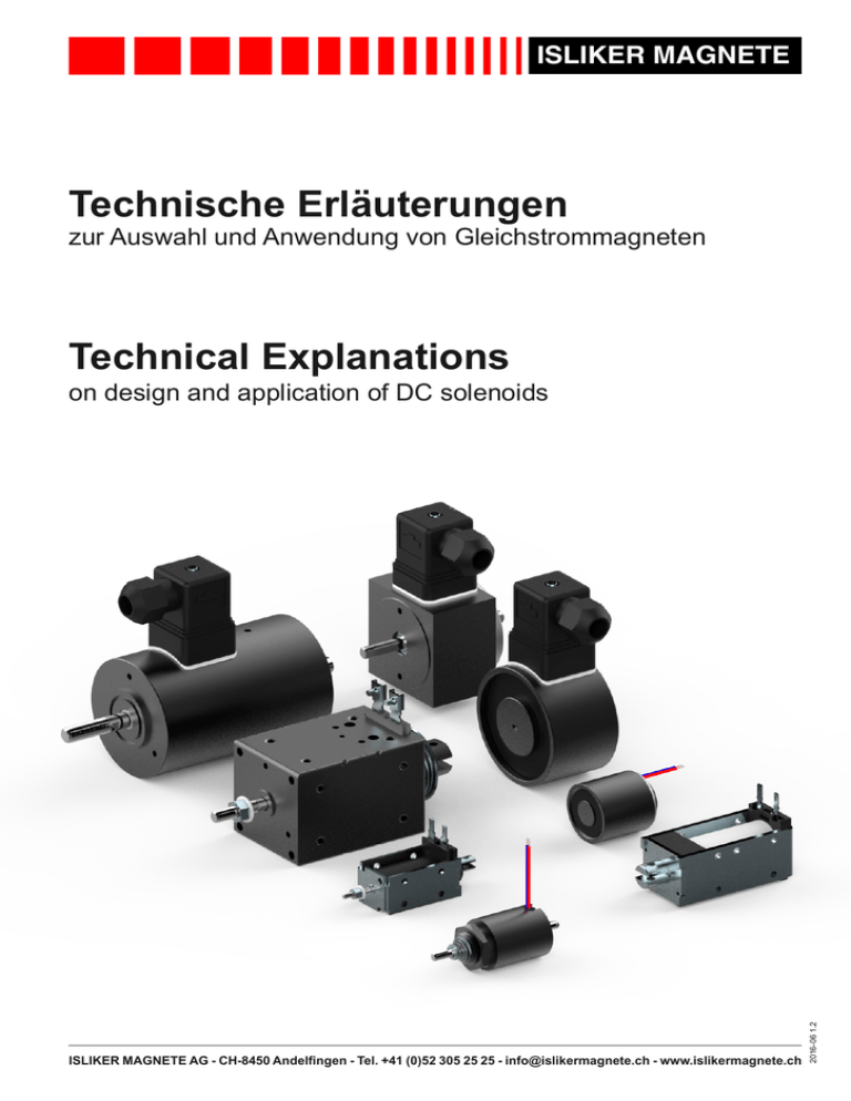
ISLIKER MAGNETE Technische Erläuterungen zur Auswahl und Anwendung von Gleichstrommagneten Technical Explanations ISLIKER MAGNETE AG - CH-8450 Andelfingen - Tel. +41 (0)52 305 25 25 - [email protected] - www.islikermagnete.ch 2016-06 1.2 on design and application of DC solenoids Technische Erläuterungen Technical Explanations ISLIKER MAGNETE 2 / 14 Inhaltsverzeichnis Index of contents 1. Allgemeine Eigenschaften der Gleichstrommagnete.............. 3 1. General characteristics of DC solenoids.................................. 3 2. Bauformen und Ausführungen.................................................. 3 2. Designs forms............................................................................. 3 3.Betriebsbedingungen................................................................. 4 3. Working conditions..................................................................... 4 4. Hub, Magnetkraft und Hubarbeit............................................... 4 4. Stroke, solenoid force and work done...................................... 4 5. Spannung, Strom und elektrische Leistung............................. 5 5. Voltage, current and electrical power....................................... 5 6. Zeitbegriffe und Nennbetriebsarten.......................................... 5 6. Duty cycle and nominal operational modes............................. 5 7. Auswahl und Dimensionierung der Magnete........................... 6 7. Selection of the solenoid dimension......................................... 6 8. Ein- und Ausschaltvorgang, Anzugs- und Abfallzeiten und deren Beeinflussungsmöglichkeiten........................................ 7 8. Switching-on and switching-off procedure, operate and release time, possibilities of influence..................................... 7 9. Temperaturen und thermische Klassen.................................. 10 9. Temperatures and thermal classes......................................... 10 10. Elektrische Ansteuerarten.........................................................11 10.Electrical control modes...........................................................11 11. Prüfung der Elektromagnete.....................................................11 11. Test specification.......................................................................11 12.Lebensdauer...............................................................................11 12.Lifetime expectancy...................................................................11 13.Schutzarten................................................................................ 12 13.Degrees of protection............................................................... 12 14.Hinweise für Montage und Betrieb.......................................... 12 14.General mounting and operating instructions....................... 12 15.Europäische Normen und Richtlinien..................................... 14 15.European standards and directives........................................ 14 16.Produktübersicht Standardmagnete....................................... 14 16.Product overview standard solenoids.................................... 14 17.Kundenspezifische Produkte................................................... 14 17.Custom solenoids..................................................................... 14 4.1.Hub................................................................................................... 4 4.2.Magnetkraft....................................................................................... 4 4.3.Hubarbeit.......................................................................................... 4 5.1.Spannung ........................................................................................ 5 5.2. Zulässige Spannungsänderung........................................................ 5 5.3.Strom................................................................................................ 5 5.4. Elektrische Leistung......................................................................... 5 6.1.Einschaltdauer.................................................................................. 5 6.2. Stromlose Pause.............................................................................. 5 6.3.Spieldauer........................................................................................ 5 6.4. Relative Einschaltdauer (% ED)....................................................... 5 6.5. Schalthäufigkeit................................................................................ 6 6.6.Nennbetriebsarten............................................................................ 6 8.1. 8.2. 8.3. 8.4. 8.5. 8.6. 8.7. 8.8. Einschaltvorgang (Fig. 2).................................................................. 7 Ausschaltvorgang (Fig. 3)................................................................. 7 Anzugs- und Abfallzeiten.................................................................. 7 Verkürzung der Anzugszeit durch Übererregung.............................. 8 Schnellerregung mittels Vorwiderstand (Fig. 4)................................ 8 Abfalldämpfung (Fig. 6).................................................................... 8 Bedämpfung von Abschaltüberspannungen..................................... 9 Freilaufdiode mit Verpolschutz (Fig. 12)......................................... 10 9.1.Umgebungstemperatur................................................................... 10 9.2.Beharrungstemperatur.................................................................... 10 9.3.Bezugstemperatur.......................................................................... 10 9.4. Abweichende Bezugstemperatur.................................................... 10 9.5. Thermische Klassen....................................................................... 10 10.1. Ansteuerung Gleichspannung.........................................................11 10.2. Ansteuerung Wechselspannung......................................................11 10.3. Ansteuerung Pulsweitenmodulation (PWM)....................................11 11.1.Prüfspannung .................................................................................11 11.2.Spannungsprüfung..........................................................................11 11.3. Wiederholte Spannungsprüfung......................................................11 14.1. Allgemeine Montagehinweise......................................................... 12 14.2.Montageanleitung........................................................................... 12 14.3. Elektrischer Anschluss.................................................................... 13 14.4.Inbetriebsetzung............................................................................. 13 14.5.Wartung.......................................................................................... 13 14.6. Reparatur oder Veränderungen...................................................... 13 14.7.Sicherheitshinweise........................................................................ 13 2.1. 2.2. 2.3. 2.4. 2.5. 2.6. 2.7. Single stroke solenoid...................................................................... 3 Return stroke solenoid...................................................................... 3 Selfholding solenoid......................................................................... 3 Bistable selfholding solenoid............................................................ 3 Rotary solenoid................................................................................. 3 Electro magnet................................................................................. 3 Permanent electro magnet............................................................... 3 4.1.Stroke............................................................................................... 4 4.2. Solenoid force................................................................................... 4 4.3. Work done ....................................................................................... 4 5.1.Voltage ............................................................................................. 5 5.2. Tolerance of the supply voltage........................................................ 5 5.3.Current.............................................................................................. 5 5.4. Electrical power................................................................................ 5 6.1. 6.2. 6.3. 6.4. 6.5. 6.6. 8.1. 8.2. 8.3. 8.4. 8.5. 8.6. 8.7. 8.8. 9.1. 9.2. 9.3. 9.4. 9.5. Time on............................................................................................. 5 Time off............................................................................................. 5 Cycle time......................................................................................... 5 Duty cycle (%).................................................................................. 5 Operating frequency......................................................................... 6 Nominal operational modes.............................................................. 6 Switching-on procedure (Fig. 2)....................................................... 7 Switching-off procedure (Fig. 3)....................................................... 7 Operate and release time................................................................. 7 Shortening the operating time by a higher voltage impulse.............. 8 Fast excitation by a series resistance (Fig. 4).................................. 8 Increasing the release time (Fig. 6).................................................. 8 Damping of voltage spikes............................................................... 9 Recovery diode with protection (Fig. 12)........................................ 10 Ambient temperature...................................................................... 10 Steady-state temperature............................................................... 10 Base temperature........................................................................... 10 Different base temperature............................................................. 10 Thermal classes............................................................................. 10 10.1. DC control mode..............................................................................11 10.2. AC control mode..............................................................................11 10.3. Pulse width modulation (PWM) control mode..................................11 11.1. Test voltage.....................................................................................11 11.2. Voltage testing.................................................................................11 11.3. Repeat voltage testing.....................................................................11 14.1. General mounting instructions........................................................ 12 14.2. Mounting instructions...................................................................... 12 14.3. Electrical termination...................................................................... 13 14.4.Commisioning................................................................................. 13 14.5.Maintanance................................................................................... 13 14.6. Adaptions and changes to the solenoid.......................................... 13 14.7. Safety instructions.......................................................................... 13 ISLIKER MAGNETE AG - CH-8450 Andelfingen - Tel. +41 (0)52 305 25 25 - [email protected] - www.islikermagnete.ch 2016-05 1.1 2.1.Einfachhubmagnet............................................................................ 3 2.2.Umkehrhubmagnet........................................................................... 3 2.3.Selbsthaltemagnet............................................................................ 3 2.4. Bistabiler Selbsthaltemagnet............................................................ 3 2.5.Drehmagnet...................................................................................... 3 2.6.Haftmagnet....................................................................................... 3 2.7. Permanent Haftmagnet.................................................................... 3 Technische Erläuterungen Technical Explanations Gleichstrommagnete besitzen einen ausserordentlich hohen Grad an Zuverlässigkeit und eine lange Lebensdauer. Der Anker kann in jeder Position des Hubes angehalten werden, ohne dass dadurch der Magnet irgendwelchen Schaden erleidet. Sollte sich also bei dem zu betätigenden Apparat eine Störung ergeben, so wird dadurch der Magnet nicht beschädigt. Das Anzugs- sowie das Abfallverhalten des Magnetankers kann durch entsprechende geometrische Auslegung, elektrische Beschaltungen oder die Ansteuerung beeinflusst werden. Der Magnet kann damit an die gestellten Einsatzbedingungen grösstenteils angepasst werden. 3 / 14 1. General characteristics of DC solenoids DC solenoids dispose an extraordinary high degree of reliability and an almost unlimited lifetime expectancy. The plunger can be stopped at any position of the stroke without damage to the solenoid, even an incident occuring on the apparatus to be operated by the solenoid, preventing the solenoid to operate to the end of the stroke can’t damage the solenoid. The operate as well as the release behavior can be widely modified with the geometrical design a variety of electrical circuits or the control mode. This enables the solenoid to be adapted to the requirements of the application. 2. Bauformen und Ausführungen 2. Designs forms 2.1. Einfachhubmagnet 2.1. Single stroke solenoid Der Einfachhubmagnet wird mittels Erregung der Spule aktiviert. Die Hubbewegung von der Hubanfangslage in die Hubendlage erfolgt durch die elektromagnetische Kraftwirkung. Die Rückstellung hat durch äussere Kräfte zu erfolgen (z.B. Feder). Es wird zwischen ziehender und stossender Ausführung unterschieden. 2.2. Umkehrhubmagnet Der Umkehrhubmagnet ist mit zwei Spulen ausgerüstet. Sein Anker kann zwei definierte Positionen einnehmen. Die Hubbewegung erfolgt, je nachdem welche der Spulen erregt wird von einer Hubendlage in die andere oder umgekehrt. Die Endstellung wird gehalten, indem die entsprechende Spule unter Spannung bleibt. 2.3. Selbsthaltemagnet Die Hubbewegung von der Hubanfangslage in die Hubendlage erfolgt durch die elektromagnetische Kraftwirkung. In der Hubendlage wird bei ausgeschaltetem Strom der Anker durch einen eingebauten Permanentmagneten gehalten. Die Rückstellung muss durch äussere Rückstellkräfte, nach dem Neutralisieren des Permanentmagneten durch umpolen der angelegten Spannung, erfolgen. 2.4. Bistabiler Selbsthaltemagnet Die Funktion ist gleich dem Prinzip des Einfachhub-Selbsthaltemagneten, jedoch mit zwei Spulen. Die Hubbewegung erfolgt je nach Erregung von einer Hubendlage in die andere. In den Hubendlagen wird bei ausgeschaltetem Strom der Anker durch einen Permanentmagneten gehalten. 2.5. Drehmagnet Die Drehbewegung erfolgt durch die elektromagnetische Kraftwirkung und ist mechanisch begrenzt. Die Rückstellung kann sowohl durch eine externe Kraft als auch durch eine Rückstellfeder erfolgen. Bei Drehmagneten mit Rückstellfeder unterscheidet man zwischen rechts- und linksdrehenden Magneten. 2.6. Haftmagnet Durch die elektromagnetische Kraftwirkung wird eine Haftkraft erzielt. Der Magnet in sich kann keine Hubarbeit verrichten. 2.7. Permanent Haftmagnet Die Funktion entspricht einem Haftmagneten, mit dem Unterschied, dass die Haltekraft stromlos erzielt wird. Die Neutralisation der Haltekraft erfolgt durch einen Stromimpuls. The single stroke solenoid is activated by connecting the coil to the electrical source. The plunger then moves from the starting to the end position of the stroke. The return movement has to be realized by an external force (i.e. by a spring). The direction of the plunger can be either in push or pull execution. 2.2. Return stroke solenoid The return stroke solenoid contains two coils. The plunger can presume two different positions. It moves in one direction to the other, depending on whether the one or the other coil is connected to the power supply. The solenoid holds its end position by keeping one of the coil connected to the power supply. 2.3. Selfholding solenoid The single stroke selfholding solenoid include a permanent magnet in the magnetic circuit. The plunger gets to its active end position by the means of only a short electrical impulse. No power is now requested to hold the plunger in the active end position, it is held there by the permanent magnet. The holding force of the permanent magnet is neutralized when the coil is energized with an electrical impulse with reverse polarity. The return movement has to be realized by an external force. 2.4. Bistable selfholding solenoid The bistable selfholding solenoid is working after the identical principal as the single stroke selfholding solenoid containing two coils. It pulls from one end position to the other, depending on whether the one or the other coil is activated with a short electrical impulse. The plunger is holding the respective end position with a permanent magnet without electrical power. 2.5. Rotary solenoid The rotary solenoid contains a specially designed magnetic circuit, which changes the basically linear magnetic force to rotate the shaft. The active rotation is obtained by connecting the coil to the electrical source. The return movement has to be achieved by external means or on request with a return spring. Rotary solenoids with a return spring assembly are distinguished between right and left rotation. 2.6. Electro magnet The electro magnet develops a holding force only, it is unsuitable to do any work e.g. to exercise any force over a certain stroke. 2.7. Permanent electro magnet This magnet is working after the same principal as the electro magnet with the difference that the holding force is maintained without continuous application of current. The neutralisation of holding force is carried out by an electrical impulse. ISLIKER MAGNETE AG - CH-8450 Andelfingen - Tel. +41 (0)52 305 25 25 - [email protected] - www.islikermagnete.ch 2016-06 1.2 1. Allgemeine Eigenschaften der Gleichstrommagnete ISLIKER MAGNETE Technische Erläuterungen Technical Explanations ISLIKER MAGNETE 4 / 14 3. Betriebsbedingungen 3. Working conditions Die Umgebungstemperatur liegt zwischen -5°C und +35°C. (Lagertemperaturbereich: -20°C bis +70°C) Die Aufstellhöhe beträgt nicht mehr als 1‘000m ü.M. Die relative Feuchtigkeit der Umgebungsluft soll 50% bei 40°C nicht überschreiten. Bei geringeren Temperaturen kann eine höhere Luftfeuchtigkeit zugelassen werden (90% bei +20°C). Die Umgebungsluft soll nicht wesentlich durch Staub, Rauch, aggressive Gase oder Dämpfe verunreinigt sein. Sollten diese Bedingungen in speziellen Anwendungen auftreten, ziehen sie Sonderausführungen der Magnete nach sich. The ambient temperatur is defined between -5°C and +35°C. (Storage temperature range: -20°C to +70°C) The altitude in place does not exceed 1’000m above sea level. The relative humidity of the environment should not exceed 50% at 40°C. At lower temperatures, higher relative humidities are permissible (90% at +20°C). The environmental air should not be polluted by dust, smoke, aggressive gases or steam. In case of those conditions appear, consult ISLIKER MAGENTE, the design of solenoids has to be adapted. 4. Hub, Magnetkraft und Hubarbeit 4. Stroke, solenoid force and work done 4.1. Hub 4.1. Stroke Der Magnethub ist der vom Anker zwischen Hubanfangslage und Hubendlage zurückgelegte Weg. Die Hubanfangslage (s1) ist die Ausgangslage des Ankers vor Beginn der Hubbewegung beziehungsweise nach Beendigung der Rückstellung. Die Hubendlage (s0) ist diejenige Stellung des Ankers, die er infolge der elektromagnetischen Kraftwirkung einnimmt. 4.2. Magnetkraft The stroke of the solenoid is the distance travelled by the plunger between starting position and end of stroke. The starting position (s1) of the plunger, is the position of the plunger before the solenoid is energized or after the plunger has been reset. The end of the stroke (s0) is the position of plunger after solenoid has been energized and the movement comes to a stop. 4.2. Solenoid force Die nominale Magnetkraft FN ist die um die Reibung verminderte mechanische Kraft des Magneten bei horizontaler Ankerlage. Sie wird in betriebswarmem Zustand und bei 90% der Nennspannung gemessen. Beim Betrieb mit Nennspannung erhöhen sich die Werte der Magnetkraft um etwa 10%. Werden in der Praxis die Magnete auf gut wärmeleitender Unterlage montiert, so kann die Magnetkraft, insbesondere durch Anpassung der Erregerleistung der Wicklung an die jeweiligen Betriebsverhältnisse, erhöht werden. Eine Erhöhung der Magnetkraft ist möglich, wenn die Umgebungstemperatur ständig unter +35°C liegt. Umgekehrt muss die elektrische Erregerleistung reduziert werden, wenn die Umgebungstemperatur im Durchschnitt über +35°C liegt, was mit einer Verminderung der Magnetkraft verbunden ist. Die Magnetkraft kann infolge natürlicher Streuungen ±10% von den Angaben in den Datenblättern abweichen. 4.3. Hubarbeit The nominal solenoid force FN is the usable mechanical force created in the direction of the active movement of the plunger in horizontal position. The solenoid force is defined by the solenoid at operating temperature and at 90% of nominal voltage. The values of the force are increased by 10% at nominal voltage over the values given in the data sheets. If the solenoids are mounted on an efficient heat sink, the solenoid force can be increased by increasing the electrical power consumtion of the coil, in accordance to the working conditions. The power consumtion of the solenoid can also be increased, and accordingly the force of the solenoid, if the average ambient temperature is under +35°C. Contrary the electrical power must be reduced if the average ambient temperature is above +35°C, which causes a reduction of the force of the solenoid. The solenoid force values shown in the datasheets can differ ±10% as a result of natural dispertion. 4.3. Work done Die Hubarbeit W entspricht dem Integral der Magnetkraft F über dem Magnethub s. Die Nennhubarbeit WN, die in den technischen Unterlagen angegeben ist, ist das Produkt aus der Nennmagnetkraft FN bei Hub­anfang und dem Magnethub s1 (Fig. 1). The work done W is calculated by the integral of the solenoid force F over its stroke s. The nominal work done WN, as shown in the data sheets, is the product of the nominal force FN at the starting position of the stroke and the stroke s1 (Fig. 1). F [N] 𝑠1 𝑊 = � 𝐹 𝑠 𝑑𝑠 ds 𝑠0 FN 𝑊𝑁 = 𝐹𝑁 × 𝑠1 WN s0 s1 s [mm] s1 = Hubanfangslage / starting position s0 = Hubendlage / end of stroke ISLIKER MAGNETE AG - CH-8450 Andelfingen - Tel. +41 (0)52 305 25 25 - [email protected] - www.islikermagnete.ch 2016-06 1.2 Fig.1: Definition Hubarbeit / Definition of work done Technische Erläuterungen Technical Explanations ISLIKER MAGNETE 5 / 14 5. Spannung, Strom und elektrische Leistung 5. Voltage, current and electrical power 5.1. Spannung 5.1. Voltage Spannungs- und Stromangaben sind bei Gleichstrom arithmetische Mittelwerte. Die Nennspannung UN eines Hubmagneten ist die Betriebsspannung. Den in den technischen Unterlagen angegeben Werten liegt, wenn nicht anders vermerkt, eine Nennspannung von 24VDC zugrunde. Bei anderen Nennspannungen können durch die unterschiedlichen Isolationsanteile in den Erregerwicklungen Abweichungen von den angegebenen Magnetkräften sowohl nach oben (meist bei <24VDC) als auch nach unten (meist bei >24VDC) auftreten (bei 230VDC bis 10%). 5.2. Zulässige Spannungsänderung Die dauernd zulässige Spannungsänderung für Gleichstrommagnete beträgt ± 10% der Nennspannung (gemäss IEC 60038). 5.2. Tolerance of the supply voltage The tolerance for nominal supply voltage for DC solenoids is ±10% (acc. IEC 60038). 5.3. Current Der Nennstrom IN ist der Strom, der sich bei Nennspannung und einer Temperatur der Erregerwicklung von +20°C einstellt. 𝐼𝑁 = 𝑃𝑁 𝑈𝑁 = 𝑈𝑁 𝑅20 Der Prüfstrom Ipr ist der Strom, auf den sich die in den technischen Unterlagen genannten Magnetkraftwerte beziehen entsprechend 90% der Nennspannung bei betriebswarmem Widerstand der Erregerwicklung RW. 𝐼𝑝𝑟 = 5.4. Elektrische Leistung 0.9 × 𝑈𝑁 𝑅𝑊 Die in den Datenblättern angegebene Nennleistung PN wird mit einer Nennspannung von 24VDC gemessen, bezogen auf den kalten Magneten. Der betriebswarme Magnet nimmt eine etwa 35% kleinere Leistung auf. Wird ein Gleichrichter eingesetzt, ist dieser für den kalten Magneten, gemäss der in den technischen Unterlagen angegebenen Leistung PN, zu dimensionieren. Ist die Umgebungstemperatur höher als +35°C, so muss die Leistungsaufnahme reduziert werden. Diese Reduktion der elektrischen Leistungsaufnahme zieht eine Reduktion der Magnetkraft nach sich. The nominal current IN is the current that results at nominal voltage and the solenoid temperature at +20°C. 𝐼𝑁 = 𝑃𝑁 𝑉𝑁 = 𝑉𝑁 𝑅20 The values of the solenoid force as shown in the data sheets are obtained at 90% nominal voltage and warm coil resistance RW with the testing current Ipr. 𝐼𝑝𝑟 = 5.4. Electrical power 0.9 × 𝑉𝑁 𝑅𝑊 The values of nominal power consumtion PN as shown in the data sheets are measured with a voltage of 24VDC, with a cold solenoid. The power consumtion at operating temperature is about 35% lower. If application needs a rectifier, it has to be dimensioned to the cold solenoid, meens PN, as shown in the data sheets. The power consumption must be reduced, if the ambient temperature exceeds +35°C. This reduction of the power consumption causes a reduction of the solenoid force. 6. Zeitbegriffe und Nennbetriebsarten 6. Duty cycle and nominal operational modes 6.1. Einschaltdauer 6.1. Time on Die Einschaltdauer ist die Zeit, die zwischen dem Einschalten und dem Ausschalten des Erregerstromes liegt. 6.2. Stromlose Pause Die stromlose Pause ist die Zeit, die zwischen dem Ausschalten und dem Wiedereinschalten des Erregerstromes liegt. 6.3. Spieldauer Die Spieldauer ist die Summe aus Einschaltdauer und der stromlosen Pause. Die Spieldauer der ISLIKER MAGNETE beträgt 300 Sekunden. Bei Miniatur- und Kleinmagneten ist die Spieldauer auf 30 Sekunden begrenzt. (DIN VDE 0580) 6.4. Relative Einschaltdauer (% ED) Die relative Einschaltdauer (% ED) ist das prozentuale Verhältnis der Einschaltdauer zur Spieldauer und wird wie folgt berechnet: % 𝐸𝐷 = 𝐸𝑖𝑛𝑠𝑐ℎ𝑎𝑙𝑡𝑑𝑎𝑢𝑒𝑟 × 100 𝐸𝑖𝑛𝑠𝑐ℎ𝑎𝑙𝑡𝑑𝑎𝑢𝑒𝑟 + 𝑠𝑡𝑟𝑜𝑚𝑙𝑜𝑠𝑒 𝑃𝑎𝑢𝑠𝑒 (= 𝑆𝑝𝑖𝑒𝑙𝑑𝑎𝑢𝑒𝑟) Time on is the time between switching on and switching off the operating current. 6.2. Time off Time off is the time between switching off the operating current and switching on again. 6.3. Cycle time Cycle time is the sum of time on and time off. The cycle time of ISLIKER solenoids is 300 seconds. DC miniature and DC small solenoids however have a cycle time of only 30 seconds. (DIN VDE 0580) 6.4. Duty cycle (%) Duty cycle is the percentage of the time on to the cycle time. It is calculated as follows: 𝑑𝑢𝑡𝑦 𝑐𝑦𝑙𝑐𝑒 (%) = 𝑡𝑖𝑚𝑒 𝑜𝑛 × 100 𝑡𝑖𝑚𝑒 𝑜𝑛 + 𝑡𝑖𝑚𝑒 𝑜𝑓𝑓 (= 𝑐𝑦𝑐𝑙𝑒 𝑡𝑖𝑚𝑒) ISLIKER MAGNETE AG - CH-8450 Andelfingen - Tel. +41 (0)52 305 25 25 - [email protected] - www.islikermagnete.ch 2016-06 1.2 5.3. Strom The voltage and power consumtion shown in the data sheets are, if not otherwise indicated, by direct current arithmetical mean values. The nominal voltage VN is the supply voltage. The values given in the data sheets for solenoid force and power consumption are generally based on nominal voltage of 24VDC. With other nominal voltages the solenoid force shown in the data sheets can differ because of different insulation amounts in the coil as well upward (mostly by <24VDC) or downwards (mostly by >24VDC). At 230VDC up to 10%. Technische Erläuterungen Technical Explanations ISLIKER MAGNETE 6 / 14 6.5. Schalthäufigkeit 6.5. Operating frequency Die Schalthäufigkeit, d.h. die maximal zulässige Schaltzahl pro Zeiteinheit, ist bestimmt durch die Anzugs- und Abfallzeiten, abhängig von der Art der Belastung, Rückstellkraft und Grösse des Magneten. 6.6. Nominal operational modes Die ISLIKER MAGNETE können für verschiedene Betriebsarten ausgelegt werden. Bei Dauerbetrieb ist die Einschaltdauer so lang, dass die Beharrungstemperatur (DIN VDE 0580) praktisch erreicht wird. Bei Aussetzbetrieb wechseln Einschaltdauer und stromlose Pause in regelmässiger oder unregelmässiger Folge, wobei die Pausen so kurz sind, dass sich der Elektromagnet nicht auf seine Bezugstemperatur (DIN VDE 0580) abkühlt. Als Kurzzeitbetrieb gilt der Betrieb, bei dem die Einschaltdauer so kurz ist, dass die Beharrungstemperatur nicht erreicht wird. Die stromlose Pause ist so lang, dass sich der Elektromagnet praktisch auf die Bezugstemperatur abkühlt. 7. Auswahl und Dimensionierung der Magnete Die Dimensionierung des Magneten erfolgt über die Hubarbeit und der relativen Einschaltdauer. Der Konstrukteur bestimmt vorderhand die Hubarbeit. Unter der gewünschten relativen Einschaltdauer wird derjenige Magnet bestimmt, dessen Hubarbeit ca. 30% grösser ist als der berechnete Wert (Kraftreserve). Der Hub entspricht nicht immer dem gewünschten Hub, aber in fast allen Fällen kann die Kraftübertragung so ausgelegt werden, dass der ganze Hub des Magneten ausgenützt werden kann (z.B. über einen Hebel). In speziellen Fällen kann die Hub-Kraft Charakteristik des Magneten den spezifischen Bedingungen der Anwendung angepasst werden. Für den Dauerbetrieb muss der Magnet mit 100% ED ausgelegt werden. Für den Aussetzbetrieb kann der Magnet mit einer wesentlich höheren elektrischen Leistung betrieben werden. Daraus resultiert eine grössere Magnetkraft im Vergleich zum Dauerbetrieb oder es kann ein kleinerer Magnet ausgewählt werden für die benötigte Hubarbeit. Die nach DIN VDE 0580 geltenden Vorzugswerte der relativen Einschaltdauer sind massgebend für die zulässig zu installierende Leistung. Die Maximalwerte der Einschaltdauer sind aus Tab. 1 ersichtlich für 300 Sekunden Spieldauer, respektive 30 Sekunden für Miniatur- und Kleinmagnete. Diese Werte dürfen nicht überschritten werden. Geschieht dies dennoch, so ist der Magnet für die nächst höhere, relative Einschaltdauer auszulegen. The ISLIKER solenoids are designed for different nominal operational modes. Continuous operation is an operation for which time on is so long that almost steady-state temperature is reached (DIN VDE 0580). Intermittent operation is an operation in which time on and time off interchange in a regular or irregular sequence, and where the time off is so short that the solenoid does not cool down to base temperature (DIN VDE 0850). Short time operation is an operation in which the time on is so short that steady-state temperature is not reached and time off is so long that the solenoid cools down almost to base temperature. 7. Selection of the solenoid dimension The selection of the size of a solenoid is made by the required work done and duty cycle. The design engineer determines first the required work done. The work done is increased by in order to allow for additional friction, then this value is looked up in the column of the previously determined duty cycle. The stroke of the now determined solenoid does not always correspond with the desired stroke. However, the stroke as required by the application, can in nearly all cases be adjusted to the standard stroke of the solenoid to take advantage of the solenoid‘s full work done (i.e. by a lever). In extraordinary cases the stroke-force characteristic of the solenoid can be adapted to the special conditions of the application. For continuous operation the solenoid must have 100% duty cycle. Intermitted operation of the solenoid allows the use of higher electrical power supply, which results in higher solenoid force compared to a solenoid for continuous operation, or a smaller solenoid may be selected for the required work done. The maximum of installed power is selected according to the nominal duty cycles of DIN VDE 0580. The maximal permissible time on, according to Tab.1 must not be exceeded, considering the cycle time of 300 respective 30 seconds for miniature and small solenoids. If the permissible time on exceeds this value, a solenoid of the next higher duty cycle must be selected. maximal zulässige Einschaltdauer [s] maximal permissible time on [s] 300s Spieldauer 30s Spieldauer 300s cycle time 30s cycle time - Economymagnete - Industriemagnete - Drehmagnete - Haftmagnete - Miniaturmagnete - Kleinmagnete - Miniature solenoids - Small solenoids duty cycle - Economy solenoids - Industrial solenoids - Rotary solenoids - Electro magnets 100% Dauerbetrieb Dauerbetrieb 100% continuous operation continuous operation 40% max. 120s max. 12s 40% max. 120s max. 12s 25% max. 75s max. 7.5s 25% max. 75s max. 7.5s 15% max. 45s max. 4.5s 15% max. 45s max. 4.5s 5% max. 15s max. 1.5s 5% max. 15s max. 1.5s relative Einschaltdauer Tab.1: Einschaltdauer für ISLIKER Standardmagnete Tab.1: Duty cycle of ISLIKER standard solenoids ISLIKER MAGNETE AG - CH-8450 Andelfingen - Tel. +41 (0)52 305 25 25 - [email protected] - www.islikermagnete.ch 2016-06 1.2 6.6. Nennbetriebsarten The operating frequency i.e. the maximum number of operations per time unit is limited by the time spent in motion and it also depends on the load, return force and the size of the solenoid. Technische Erläuterungen Technical Explanations ISLIKER MAGNETE 7 / 14 8. Ein- und Ausschaltvorgang, Anzugs- und Abfallzeiten und deren Beeinflussungsmöglichkeiten 8. Switching-on and switching-off procedure, operate and release time, possibilities of influence 8.1. Einschaltvorgang (Fig. 2) 8.1. Switching-on procedure (Fig. 2) Beim Einschalten der Erregerwicklung des Magneten steigt der Strom entlang einer e-Funktion an, weil durch die Ruhelage des Ankers die Induktivität der Spule konstant ist. Der Strom steigt nun an, bis er den Wert IB erreicht. Daraufhin setzt sich der Anker mit der angehängten Last in Bewegung. Während der Hubbewegung steigt die Induktivität, indem der Anker den Luftspalt stetig verkleinert und dadurch den Eisenkreis schlussendlich schliesst. So ergibt sich eine Erhöhung der Impedanz, welche eine Abnahme des Stromes zur Folge hat. Nach Erreichen der Hubendlage bleibt die Induktivität konstant. Der Strom steigt gemäss einer e-Funktion auf den Nennwert. A soon as the exciting coil has been switched on, the current increases, according to an e-function, the inductivity of the coil being constant, since the plunger stays at its resting position. As the current increases till it reaches the IB value the plunger begins to move with its load. The inductivity increases during the movement, as the plunger closes the magnetic circuit. The increase of the actual impedance during the movement of the plunger reduces the current. The inductivity remains constant as the plunger reaches its final position. From this moment on the current increases according to an e-function to its nominal value. Spannung / Voltage Spannung / Voltage lB Strom / Current Strom / Current Hub / Stroke Hub / Stroke t12 t1 t21 t22 t2 t1 = Anzugszeit / Operate time t11 = Ansprechzeit / Set delay time t12 = Hubzeit / Stroke time t2 = Abfallzeit / Release time t21 = Abfallverzug / Reset delay time t22 = Rücklaufzeit / Return time Fig. 2: Einschaltvorgang / Switching-on procedure Fig. 3: Ausschaltvorgang / Switching-off procedure 8.2. Ausschaltvorgang (Fig. 3) Beim Ausschaltvorgang muss die im Magneten gespeicherte Energie vernichtet werden. Das Öffnen der Schaltkontakte hat einen Lichtbogen zur Folge, über welchem dem Magneten anfänglich noch Energie zufliesst. Nachdem der Lichtbogenwiderstand jedoch einen gewissen Wert erreicht hat, setzt eine Umkehr des Energieflusses ein. Zu diesem Zeitpunkt hat die Spannung den Nullpunkt erreicht. Der Strom behält seine Richtung bei und nimmt weiter ab. Die Spannung strebt nun bei umgekehrter Energierichtung einem negativen Höchstwert zu. Damit erreicht der Strom einen Nullwert, und der Lichtbogen erlischt. Die Spannung klingt nunmehr gemäss einer e-Funktion ab. Während des nun einsetzenden Ankerrücklaufes und der damit verbundenen Induktivitätsänderung steigt die negative Spannung nochmals leicht. Diese Spannungsspitze ist jedoch bedeutend kleiner als die vorhergehende. Die Höhe der Abschaltspannungsspitze ist im wesentlichen vom Energieinhalt der Spule des Magneten und von der Öffnungsgeschwindigkeit des Stromkreises abhängig. 8.3. Anzugs- und Abfallzeiten Die Anzugszeit ist die Zeit vom Einschalten des Erregerstromes bis zum Erreichen der Hubendlage. Die Abfallzeit ist die Zeit vom Ausschalten des Erregerstromes bis zum Erreichen der Hubanfangslage. Die Werte in den technischen Unterlagen für die Anzugs- und Abfallzeiten sind Richtwerte und gelten für eine Nennspannung von 24VDC, bei betriebswarmen Magneten und bei einer Belastung mit 70% der angegebenen Magnetkraft. 8.2. Switching-off procedure (Fig. 3) The energy held back within the solenoid has to be neutralized by disconnecting the solenoid from the supply voltage. Opening the contacts of the switch causes a spark. The solenoid still receives energy over this spark at the beginning of the movement of the contacts. However, as soon as the resistance of the spark reaches a certain value the voltage across the spark reaches zero and a return of energy commences. The current still keeps its direction but diminishes more and more. The voltage, with an opposite polarity, surges to its most extreme negative value, the current arrives at zero and the spark extinguishes. The voltage of the coil is now reduced according to an e-function, with the plunger still in the active position. With the beginning of the return of the plunger and accordingly the change of the inductivity, the negative voltage is considerably less significant than the one at zero current. The negative switching-off voltage summit depends thus on the energy of the solenoid as well as on the opening speed of the contacts of the switch. 8.3. Operate and release time Operate time is the time from switching-on the coil until the armature reaches the end of the stroke. Release time is the time between switching-off the current until the start position of the plunger is reached. The times given in the data sheets are standard values at nominal voltage of 24VDC, for a warm solenoid and with a load of 70% of the solenoid force. ISLIKER MAGNETE AG - CH-8450 Andelfingen - Tel. +41 (0)52 305 25 25 - [email protected] - www.islikermagnete.ch 2016-06 1.2 t11 Technische Erläuterungen Technical Explanations ISLIKER MAGNETE 8 / 14 8.4. Verkürzung der Anzugszeit durch Übererregung Bei der Übererregung wird durch kurzzeitige erhöhte Anschlussspannung die Magnetkraft erhöht und damit die Anzugszeit verkürzt. Die Übererregung darf jedoch nur solange andauern, wie dies für die Funktion unbedingt erforderlich ist, da sonst die Erregerwicklung durch Überhitzung zerstört werden kann. Nach erfolgter Hubbewegung muss die Spannung auf den zulässigen Wert, welcher der relativen Einschaltdauer entspricht, herabgesetzt werden. 8.5. Schnellerregung mittels Vorwiderstand (Fig. 4) Bei der Schnellerregung wird durch das Vorschalten eines Widerstandes RV der Gesamtwiderstand vergrössert. Dabei wird die für den Stromanstieg entscheidende elektromagnetische Zeitkonstante verringert und somit die Anzugszeit des Magneten entsprechend verkürzt. Die Grösse des Vorwiderstandes RV ergibt sich aus dem ohmschen Spulenwiderstand R20 durch die Beziehung: 𝑈𝐴 − 𝑈𝑁 𝑈𝑁 The solenoid force can be increased with a short impulse of a higher supply voltage thus the operate time is shortened. This impulse must last only as long as absolutely necessary to perform the required function, otherwise the coil will be damaged. After reaching the end of stroke position the supply voltage must be reduced to its maximum permissible voltage as determined by the duty cycle of the solenoid. 8.5. Fast excitation by a series resistance (Fig. 4) The total resistance will be increased by adding a resistance in series with the solenoid. The electromagnetic time constant, decisive for the momentary increase of current, will be decreased correspondingly thus decreasing the operating time of the solenoid. The value of the series resistance RV is calculated from the nominal ohmic solenoid resistance R20 by the following formula: 𝑅𝑉 = 𝑅20 × 𝑉𝐼 − 𝑉𝑁 𝑉𝑁 UA = Anschlussspannung UN = Nennspannung des Magneten VI = Input voltage VN = Nominal voltage of the solenoid Soll die Anzugszeit z.B. nur 60% des Listenwertes betragen, dann muss die Netzspannung, entsprechend Fig. 5, um den Faktor 2.5 erhöht werden. Daraus ergibt sich RV als: If, for example, the operate time must be only 60% of its nominal value, then it is necessary, to increase the supply voltage by a factor of 2.5 as found in Fig. 5. Then RV is calculated as: 𝑅𝑉 = 𝑅20 × + 2.5 × 𝑈𝑁 − 𝑈𝑁 = 𝑅20 × 1.5 𝑈𝑁 S R20 , L UA VI UN VN UA -UN - UA VI � UN VN 6 4 2 0 Fig. 4: Schnellerregung / Fast exitation S 20 40 60 80 100 t [%] 8.6. Increasing the release time (Fig. 6) Eine Abfallverzögerung des Magneten kann durch Schalten einer Diode und einem Widerstand in Serie, parallel zum Magneten erreicht werden. Erfahrungsgemäss sollte der Parallelwiderstand zwischen dem ein bis 4-fachen Wert des ohmschen Magnetwiderstandes liegen. Die Berechnung des Parallelwiderstandes RP für eine gewünschte Abfallverzögerung wird an folgendem Beispiel gezeigt: Die Abfallzeit soll auf den doppelten Wert erhöht werden, was ein Widerstandsverhältnis von 1.7 ergibt (Fig. 7). 𝑡𝑉 =2 𝑡𝑁 0 Fig. 5: Umrechnungsfaktor / Conversion factor 8.6. Abfalldämpfung (Fig. 6) + 8 2.5 × 𝑉𝑁 − 𝑉𝑁 = 𝑅20 × 1.5 𝑉𝑁 UA VI � UN VN RV VI -VN 𝑅𝑉 = 𝑅20 × 𝑅𝑃 = 1.7 𝑅20 A certain delay in armature movement of the solenoid can be obtained by a diode and a resistance in series, parallel to the solenoid. The parallel resistance should be determined by tests and it should be between one to 4 times the value of the ohmic solenoid resistance. The calculation of the parallel resistance RP for a required delay of armature movement is shown on the following example: The release time has to be doubled which gives us a resistance ratio of 1.7 (Fig. 7). 𝑡𝑉 4 =2 𝑡𝑁 3.5 𝑅𝑃 = 1.9 𝑅𝑆 3 V R20 , L RP UA VI 2.5 2 1.5 1 Fig. 6: Abfalldämpfung / Increase of release time 0 2 4 6 𝑡𝑉 =2 𝑡𝑁8 Fig. 7: Widerstandsverhältnis / Resistance ratio 10 𝑅𝑃 = 1.7 𝑅20 ISLIKER MAGNETE AG - CH-8450 Andelfingen - Tel. +41 (0)52 305 25 25 - [email protected] - www.islikermagnete.ch 2016-06 1.2 𝑅𝑉 = 𝑅20 × 8.4. Shortening the operating time by a higher voltage impulse Technische Erläuterungen Technical Explanations ISLIKER MAGNETE 9 / 14 8.7. Bedämpfung von Abschaltüberspannungen 8.7. Damping of voltage spikes Die Induktivität verursacht besonders bei grösseren Gleichtrommagneten hohe Abschaltüberspannungen, die zum Durchschlagen der elektrischen Isolation führen können. Besonders unerwünscht ist die Abschaltüberspannung, wenn der Magnet elektronisch angesteuert wird, da die Spannungsspitzen zur Zerstörung der Halbleiterbauelemente führen können. 8.7.1. Diode mit Zenerdiode (Fig. 8) 8.7.1. Diode with zener-diode (Fig. 8) Die Zenerdiode ist nur dann wirksam, wenn die Abschaltüberspannung grösser als die Zenerspannung ist. Die Diode sorgt dafür, dass in Durchlassrichtung kein Strom über die Zenerdiode fliessen kann. Vorteile: - sehr kurze Abfallzeiten - geringe Überspannungsspitzen - definierte Überspannungsspitzen Nachteile: - nur für kleine elektrische Leistungen geeignet 8.7.2. Varistorbeschaltung (Fig. 9) The zener-diode is only effective as long as the value of the spike to be switched off is higher than the zener voltage. The additional diode ensures that no current flows via the zener diode in the conducting direction. Advantages: - very short release time - small transient voltage - defined transient voltage Disadvantages: - for small electrical power only 8.7.2. Varistor method (Fig. 9) Der Varistor wird so ausgelegt, dass er bei der Nennspannung UN einen sehr hohen Widerstand besitzt. Der Widerstand des Varistors verringert sich aber erheblich bei Auftreten der Abschaltüberspannung. Vorteile: - preiswert - geringe Abfallverzögerung Nachteile: - nicht geeignet für hohe Schaltfrequenzen + DC solenoids and particulary large ones, show the phenomenon of reverse polarity voltage spikes when the operating current is disconnected. They are able to damage coil insulation. This situation is aggravated with semiconductor switches as the switching times are very short and the semiconductor devices themselves are very sensitive to voltage spike destruction. The varistor has a high resistance at nominal voltage VN. However when the voltage spike occurs the resistance of the varistor drops considerably, thus damping the peak voltage. Advantages: - low priced - delay time increased only moderately Disadvantages: - not qualified for high switching frequency + S S R20 , L U UA VI UA VI R20 , L V1 V2 - - Fig. 8: Schaltung mit Zenerdiode / Zener diode circuit 8.7.3. Brückengleichrichter 8.7.3. Bridge rectifier Wird die Schaltung wechselstromseitig vorgenommen, so wird die Abschaltüberspannung vollständig gedämpft. Vorteile: - preiswert - geeignet für alle elektrischen Leistungen Nachteile: - grosse Abfallverzögerung 8.7.4. RC-Glied (Fig. 10) If switching-on and -off is done on the AC side of the rectifier, any switch-off spikes are damped completely. Advantages: - low priced - qualified for any electrical power Disadvantages: - high release time 8.7.4. RC module (Fig. 10) Vorteile: - geringe Schaltüberspannungen - geringe Abfallverzögerung Nachteile: - mit zunehmender elektr. Leistung aufwendig 8.7.5. Freilaufdiode (Fig. 11) Advantages: - small switch-off spikes - small delaying armature movement Disadvantages: - costly with increasing electrical power 8.7.5. Recovery diode (Fig. 11) Vorteile: - preiswert - sehr guter Kontaktschutz Nachteile: - grosse Abfallverzögerung + Fig. 9: Varistorbeschaltung / Varistor circuit Advantages: - low priced - efficient switch contact protection Disadvantages: - high release time + S S Fig. 10: Beschaltung mit RC-Glied / RC module circuit R20 , L V - Fig. 11: Schaltung mit Freilaufdiode / Recovery diode circuit ISLIKER MAGNETE AG - CH-8450 Andelfingen - Tel. +41 (0)52 305 25 25 - [email protected] - www.islikermagnete.ch 2016-06 1.2 - UA VI R20 , L RP UA VI C Technische Erläuterungen Technical Explanations ISLIKER MAGNETE 10 / 14 8.8. Freilaufdiode mit Verpolschutz (Fig. 12) 8.8. Recovery diode with protection (Fig. 12) Häufig wird zur Freilaufdiode zusätzlich eine Verpolschutz Diode eingebaut. Diese verhindert bei einem versehentlich verkehrt angeschlossenen Magneten einen Kurzschluss auf der Zuleitung und somit die Zerstörung der Freilaufdiode. Die Verpolschutzdiode ist gemäss dem Nennstrom des Magneten zu dimensionieren. S IN V1 UA VI UN = UA - 0.7V VN = VI - 0.7V Fig. 12: Beschaltung mit Freilaufdiode und Verpolschutz Recovery diode with protection circuit R20 , L + To the recovery diode usually there is build in a protection diode. This proctection diode will prevent a short circuit and in same time a damage of the recovery diode in case of a wrong polarity of supply voltage. The protection diode has to be applied according the nominal current of solenoid. V2 - 9. Temperaturen und thermische Klassen 9. Temperatures and thermal classes 9.1. Umgebungstemperatur 9.1. Ambient temperature Die Umgebungstemperatur ist die Durchschnittstemperatur für Betriebsmittel an definierten Stellen seiner Umgebung. 9.2. Beharrungstemperatur Ambient temperature is the mean temperature of the environment of the solenoid. 9.2. Steady-state temperature Die Beharrungstemperatur stellt sich ein, wenn sich zu- und abgeführte Wärme im Gleichgewicht halten. 9.3. Bezugstemperatur Steady-state temperature will result when supplied and dissipated heat hold themselves in balance. 9.3. Base temperature Die Bezugstemperatur für Elektromagnete beträgt normalerweise +35°C. Sie kann abweichen entsprechend ob der Magnet an Maschinenteile montiert wird, welche eine höhere oder tiefere Temperatur haben. 9.4. Abweichende Bezugstemperatur Base temperature of a solenoid is normally +35°C. It can be different if the solenoid is fitted to machine components which has a higher or lower temperature. 9.4. Different base temperature Die Magnete sind auch bei abweichender Bezugstemperatur einsetzbar, wenn die zulässige ED mit dem entsprechenden Umrechnungsfaktor multipliziert wird. Zur Ermittlung der relativen ED dient Fig. 13. The solenoids can also be used in environments with different base temperature. In this case the duty cyle must be modified by a suitable factor. The diagram of the correcting factor of the duty cycle is given in Fig. 13. Beispiel: Ein Magnet mit 40% ED soll bei einer Beharrungstemperatur von +50°C eingesetzt werden. Mit Hilfe der Fig. 13 ergibt sich der Faktor 0.8 für die maximal zulässige Betriebs-ED: Example: A solenoid with 40% duty cycle is to be used at a base temperature of +50°C. With Fig. 13 the correcting factor is found to be 0.8 and so the maximum allowed duty cycle wil be: 40% 𝑑𝑢𝑡𝑦 𝑐𝑦𝑐𝑙𝑒 × 0.8 = 32% 𝑑𝑢𝑡𝑦 𝑐𝑦𝑐𝑙𝑒 40% 𝐸𝐷 × 0.8 = 32% 𝐸𝐷 9.5. Thermal classes Die Isolierstoffe sind gemäss DIN VDE 0580 entsprechend ihrer Temperaturbeständigkeit in thermische Klassen eingeteilt. Die Grenztemperatur ist die für die Wicklung und andere Isolierstoffe maximal zulässige Temperatur. Die Grenzübertemperatur ist die Differenz aus Grenztemperatur minus Bezugstemperatur (normal +35°C) sowie aus einer Heisspunktdifferenz von 5°C (Tab. 2). Thermische Klasse Thermal class Bezugstemperatur [°C] Base temperature [°C] 80 60 40 20 0 The insulation materials used are according to DIN VDE 0580 which grades these materials into thermal classes (Tab. 2). Temperature limit is the highest permissible temperature of a solenoid or any part of it. The over temperature limit is the difference between the temperature limit and the base temperature (usually +35°C) including a superheat difference of 5°C. 0.0 0.2 0.4 0.6 0.8 1.0 1.2 ED Faktor / duty cycle factor Fig. 13: ED Korrekturfaktor / Duty cycle correcting factor Grenztemperatur Temperature limit Grenzübertemperatur Over temperature limit Y 90°C 50K A 105°C 65K E 120°C 80K B 130°C 90K F 155°C 115K H 180°C 160K 200 200°C 160K Tab. 2: Thermische Klassen / Thermal classes (DIN VDE 0580) ISLIKER MAGNETE AG - CH-8450 Andelfingen - Tel. +41 (0)52 305 25 25 - [email protected] - www.islikermagnete.ch 2016-06 1.2 9.5. Thermische Klassen Technische Erläuterungen Technical Explanations ISLIKER MAGNETE 11 / 14 10.Elektrische Ansteuerarten 10.Electrical control modes 10.1.Ansteuerung Gleichspannung 10.1.DC control mode Die ISLIKER MAGNETE sind Gleichstrommagnete und können direkt mit Gleichspannung betrieben werden. 10.2.AC control mode Für eine Ansteuerung mit Wechselspannung ist ein Brückengleichrichter zu verwenden. Die maximal zulässigen Ströme für Magnete mit eingebauten Gleichrichtern sind unbedingt zu beachten. Für höhere Ströme ist ein entsprechend dimensionierter Gleichrichter im Schaltschrank unterzubringen. 10.3.Ansteuerung Pulsweitenmodulation (PWM) Dabei wird die Gleichspannung der Einspeisung mit Hilfe einer Elektronik in eine gepulste Betriebsspannung umgewandelt. Dies wird mittels eines Mikroprozessors erreicht, der einen Leistungshalbleiter auf einer Leiterplatte ansteuert. Die Ansteuerung des Magneten ist dabei frei programmierbar. Diese Ansteuerart hat den Vorteil, dass sich die Magneteigenschaften optimal an die jeweilige Anwendung anpassen lassen. Operation with AC power supply will be realised by using a bridge rectifier. The values for maximum admissible current for solenoids with built-in rectifier must be respected. For higher currents please install higher rated rectifiers in the control box. 10.3.Pulse width modulation (PWM) control mode In this case the direct current of power supply will be converted with the help of an electonic system to a pulsed voltage signal. This conversion is realised by a microprozessor controling a power semiconduktor device. Thereby it’s possible to control the solenoid individually. This control mode has the advantage that solenoid characteristics can be adapted to the respectiv application. 11.Prüfung der Elektromagnete 11.Test specification 11.1.Prüfspannung 11.1.Test voltage Sämtliche Magnete werden vor Auslieferung auf ihre Spannungsfestigkeit geprüft. Die Prüfung wird mit sinusförmiger Wechselspannung mit einer Frequenz von 50Hz durchgeführt. Die Höhe der Prüfspannung, aufgezeigt in Tab. 3, richtet sich nach der Nennspannung des Magneten. Die Prüfspannungen sind gemäss DIN VDE 0580 festgelegt und gelten für die Überspannungskategorie III (EN 60664-1). Nennspannung Prüfspannung Ueff für Schutzklasse I und III All solenoids are tested for their dielectric strehgth before they leave the factory. The test voltage is a alternating voltage with a frequency of 50Hz with a value dependent on nominal voltage of solenoid as shown in Tab. 3. Test voltages are defined according DIN VDE 0580 and applies to overvoltage category III (EN 60664-1). Nominal voltage Test voltage Veff for protection classes I and III ≤ 50V 500VAC ≤ 50V 500VAC > 50 ... ≤ 100V 800VAC > 50 ... ≤ 100V 800VAC > 100 ... ≤ 150V 1‘400VAC > 100 ... ≤ 150V 1‘400VAC > 150 ... ≤ 300V 2‘200VAC > 150 ... ≤ 300V 2‘200VAC > 300 ... ≤ 600V 3‘300VAC > 300 ... ≤ 600V 3‘300VAC Tab. 3: Prüfspannungen gemäss DIN VDE 0580 11.2.Spannungsprüfung Die Prüfspannung Ueff wird zwischen der Erregerwicklung und den berührbaren Metallteilen des Gerätes angelegt und für 1s am Prüfling belassen (Standard Magnete bis UN < 600V). Die Prüfung gilt als bestanden, wenn weder Durchschlag noch Überschlag auftritt. 11.3.Wiederholte Spannungsprüfung Die bei ISLIKER MAGNETE durchgeführte Spannungsprüfung soll nicht wiederholt werden. Eine allfällige zweite Prüfung darf nur mit 80% der definierten Prüfspannung gemäss DIN VDE 0580 vorgenommen werden. 12.Lebensdauer Die Lebensdauer der Gleichstrommagnete (Anzahl Schaltspiele) ist nicht nur von der Bauart, sondern auch in starkem Masse von äusseren Bedingungen, wie Art und Höhe der Belastung und der Einbaulage, abhängig. Eine optimale Lebensdauer wird erreicht, wenn der Magnet mit maximal 75% seiner Nennkraft beaufschlagt wird. Mit PTFE-Lagern ausgerüstete Magnete dürfen nicht geschmiert werden, da dadurch die Lebensdauer der Lager herabgesetzt wird und die Lagerstellen zum Kleben neigen. Tab. 3: Test voltages according DIN VDE 0580 11.2.Voltage testing The test voltage Veff is applied between the solenoid body and the coil windings for a period of 1s. (For standard products with nominal voltages up to 600V) The test is passed when no breakdown of the insulation occurs. 11.3.Repeat voltage testing The voltage testing by ISLIKER MAGNETE must not be repeated. A second test, performed on special customer request, should only be conducted at 80% of the previous test voltage (according DIN VDE 0580). 12.Lifetime expectancy The lifetime expectancy of the DC solenoids depends not only on design, but also to a considerable extent on external conditions, radial loads, dust of various kinds, are specially harmful, and reduce the normal lifetime expectancy considerable. To achieve a hight lifetime expectancy, apply solenoid with a maximum of 75% of his nominal force. Solenoids designd with PTFE-bushings must not be lubricated under any circumstances otherwise the lifetime of the bushings will be reduced. ISLIKER MAGNETE AG - CH-8450 Andelfingen - Tel. +41 (0)52 305 25 25 - [email protected] - www.islikermagnete.ch 2016-06 1.2 10.2.Ansteuerung Wechselspannung ISLIKER solenoids are DC solenoids and can be operated directly by direct current. Technische Erläuterungen Technical Explanations 13.Degrees of protection Die in den Datenblättern angegebenen Schutzarten sind gemäss EN 60529 bezeichnet. Sie definieren den Umfang des Schutzes durch ein Gehäuse gegen den Zugang von gefährlichen Teilen (Personenschutz), gegen Eindringen von Festkörpern und/oder gegen Eindringen von Wasser. Die Schutzart wird mittels IP-Code angegeben. Schutzart IP00 IP20 IP40 12 / 14 Schutzumfang (1te Ziffer: Festkörperschutz / 2te Ziffer: Wasserschutz) 0: kein Schutz 0: kein Schutz 2: Fingerschutz, Fremdkörper ≥ Ø12mm 0: kein Schutz 4: Drahtschutz, Fremdkörper ≥ Ø1mm 0: kein Schutz The protection classes mentioned in the data sheets are designated in accordance with EN 60529. They define the extent of protection provided by an enclosure against access to hazardous parts (protection of person), against ingress of solid foreign objects and/ or against ingress of water. The degree of protection is indicated by the IP-Code. Degree of protection IP00 IP20 IP40 5: Schutz gegen Staub IP54 4: Schutz gegen Spritzwasser aus beliebigem Winkel 5: Schutz gegen Strahlwasser aus beliebigem Winkel Tab. 4: Schutzarten gemäss EN 60529 (1st digit: solid foreign objects / 2nd digit: water ingress) 0: no protection 0: no protection 2: finger protection, foreign objects ≥ Ø12mm 0: no protection 4: wire protection, foreign objects ≥ Ø1mm 0: no protection 5: protection against dust IP54 6: Vollständiger Schutz, Staubdicht IP65 Scope of protection 4: protection against splashing water from any direction 6: total protection, dustproof IP65 5: protection against water jet from any direction Tab. 4: Degrees of protection according EN 60529 14.Hinweise für Montage und Betrieb 14.General mounting and operating instructions 14.1.Allgemeine Montagehinweise 14.1.General mounting instructions Elektromagnete können in bliebiger Einbaulage eingesetzt und betrieben werden. Dabei ist das Gewicht des Magnetankers, je nach Einbaulage und entsprechend dem Einsatzfall zu berücksichtigen. Bei der Montage und Inbetriebnahme von Elektromagneten ist darauf zu achten, dass zuerst die mechanische Befestigung und anschliessend der elektrische Anschluss ausgeführt wird. Montage, elektrischer Anschluss und Inbetriebnahme sind ausschliesslich durch Fachpersonal auszuführen! 14.2.Montageanleitung Unsere Elekromagnete sind, je nach Typ, mit unterschiedlichen Befestigungsarten wie Flansch, axialer oder zentraler Verschraubung oder seitlicher Befestigung erhältlich. Die detaillierte Befestigungsart ist aus den einzelnen Datenblättern zu entnehmen. Es ist darauf zu achten, dass die Befestigungsschrauben nicht zu lang sind und gemäss der in den Datenblättern angegebenen Einschraubtiefen gewählt werden, da sonst die Magnetspule beschädigt werden kann. • Bei Hubmagneten ist der Magnetanker mit dem zu betätigenden Maschinenteil durch Laschen oder Gabelkopf, auf keinen Fall starr, sondern gelenkig, mit allseitigem Spiel, mechanisch zu verbinden. Eine extern angebrachte Rückstellfeder ist so auszuwählen, dass deren Federkennlinie der Hub-Kraft Kennlinie des Magneten angepasst ist. Um eine lange Lebensdauer zu erreichen, ist zu beachten, dass die Kräfte in axialer Richtung abgenommen werden. • Bei Haftmagneten ist darauf zu achten, dass die Ankerplatte eben und ohne Luftspalt auf der Haftfläche aufliegt. Zur optimalen Nutzung der Haltekraft, sollten die Kräfte axial zum Magneten angreifen. • Bei Drehmagneten ist die Drehbewegung der Achse extern zu begrenzen. Dabei sind grössere, in Achsrichtung wirkende Kräfte, zu vermeiden. Solenoids can be mounted in any position, the shaft upright horizontal, or any position desired. It’s the weight of the armature, depending on the installation position and in accordance with the application to be taken into account. During installation and commissioning of solenoids is to make sure that first the mechanical attachment and then the electrical connection is performed. Installation, electrical connection and commissioning are carried out exclusively by qualified personnel! 14.2.Mounting instructions On our solenoid types, a multitude of tapped holes are provided to allow a variety of mounting positions. The fixing screws should not exceed the maximum admissible length as shown on the respective solenoid data sheets, otherwise damage to the coil winding may occur. • On linear stroke types the plunger of solenoid and the machine part to be operated, should be connected by bracket or steering heads, in no case a rigid connection should be made. Plunger has to be brought into the starting position by external means, like springs, in a way that it corresponds to the stroke-force characteristics of the solenoid. To improve mechanical life, the load must be in line with the plunger, side loads must be kept to a minimum. • On electro magnets make sure that the anchor plate rests on the adhesive surface smooth and without an air gap. For optimal use of the holding force, the forces should attack axially to the magnet. • On rotary solenoids the rotating motion of the solenoids should be limited by external buffers in order to get a high lifetime expectancy. Stronger forces in axial direction should also be limited by external devices. ISLIKER MAGNETE AG - CH-8450 Andelfingen - Tel. +41 (0)52 305 25 25 - [email protected] - www.islikermagnete.ch 2016-06 1.2 13.Schutzarten ISLIKER MAGNETE Technische Erläuterungen Technical Explanations ISLIKER MAGNETE 13 / 14 14.3.Elektrischer Anschluss 14.3.Electrical termination Folgende Anschlussarten sind erhältlich: Following terminations are available: Anschlussart Baureihe Freie Litzen Steckanschluss Klemmengehäuse Universalanschluss GI / UG x x x - GK x - - GE - x GM x GT / GTP Termination Type Lead wire Plug connection Terminalbox Universal termination GI / UG x x x - - GK x - - - x x GE - x x x - - x GM x - - x x x - - GT / GTP x x - - GMH - - - x GMH - - - x GCH x - - - GCH x - - - DGV x x - - DGV x x - - Tab. 5: Elektrische Anschlussarten Tab. 5: Electrical terminations Je nach Anschlussart ist der korrekte elektrische Anschluss auszuführen. Gemäss dem Typenschild ist die Spannungsversorgung auszuwählen (DC oder AC mit Gleichrichter) und die Leistungsdimensionierung sicher zu stellen. Die Stromaufnahme des Magneten errechnet sich nach Kapitel 5.3. Der Erdungsanschluss muss bei Nennpannungen grösser 50V angeschlossen werden. Die Polarität der Versorgungspannung ist je nach Magnettyp zu beachten. Details zum elektrischen Anschluss sind aus den entsprechenden Datenblättern zu entnehmen. Depending on the termination the correct electrical connection is to be executed. According to the type plate is to select the power supply (DC or AC with rectifier) and provide the power dimensioning. The power consumption of the solenoid is calculated according to section 5.3. The ground terminal must be connected at nominal voltages over 50V. The polarity of the supply voltage must be observed depending on the type of solenoid. Electrical details can be taken from the corresponding data sheets. 14.4.Inbetriebsetzung Vor der Inbetriebnahme ist die Anschlussspannung mit den Angaben auf dem Typenschild zu prüfen und der korrekte Anschluss sicherzustellen. (Der Spannungsabfall in der Zuleitung ist dabei zu beachten). Ein Betrieb des Elektromagneten ausserhalb der spezifizierten Daten oder Umweltbedingungen kann zur Schädigung führen! 14.5.Wartung 14.4.Commisioning Befor commisioning, check the nominal voltage indicated on the type plate and the correctly installed termination. Data written on type plate must correspond to the operating voltage. (be aware of voltage drop because of long supply lines). Operation of solenoids out of specifications or environmental conditions may cause damaging! 14.5.Maintanance 14.6.Reparatur oder Veränderungen Reparaturen an den Elektromagneten dürfen ausschliesslich vom Hersteller durchgeführt werden. Durch unsachgemäss ausgeführte Reparaturen können Sach- oder sogar Personenschäden entstehen. Eine nachträgliche Bearbeitung von Elektromagneten ist nicht erlaubt, da durch das Eindringen von Fremdteilen die Funktion des Gerätes beeinträchtigt werden kann. In solchen Fällen erlischt der Garantieanspruch! 14.7.Sicherheitshinweise All our solenoids are maintenance-free. The movable parts of the solenoid are to be kept free of grease and clean. The bonding surfaces of the electro magnets must be kept clean and not mechanically damaging. (holding force loss) For any work on the parts is to pay attention that they are free of electrical voltage. 14.6.Adaptions and changes to the solenoid Repairs to the solenoid may only be carried out by the manufacturer. By incorrect performed repairs may arise material damage or even personal injury. Machining of the solenoid itself is prohibited since its function may be jeopardized. In such cases any guarantee is void! 14.7.Safety instructions Der Betrieb von Elektromagneten ausserhalb der Spezifikationen kann zur Zerstörung derselben führen und Personen gefährden. The operation of solenoids outside the specifications may cause the destruction of the same and endanger people. Elektromagnete können sich im Betrieb erheblich erwärmen. Geeignete Schutzmassnahmen vorsehen. Solenoids can significantly heat up during operation. Provide suitable safety precautions. Elektromagnete mit eingebauten Permanentmagneten (Typ: GTP/GMH/GCH) erzeugen magnetische Felder. Nicht in die Nähe von empfindlichen elektronischen Geräten bringen, wie z.B. Herzschrittmachern. Solenoids with build-in permanent magnet (type: GTP /GMH/GCH) generate magnetic fields. Not placed in the vicinity of sensitive electronic equipment, such as pacemakers. ISLIKER MAGNETE AG - CH-8450 Andelfingen - Tel. +41 (0)52 305 25 25 - [email protected] - www.islikermagnete.ch 2016-06 1.2 Alle unsere Elektromagnete arbeiten wartungsfrei. Die beweglichen Teile der Hubmagnete sind fettfrei und sauber zu halten. Die Haftflächen der Haftmagnete sind sauber zu halten und mechanisch nicht zu beschädigen. (Haftkraftverlust) Bei jeglichen Arbeiten an den Teilen ist darauf zu achten, dass diese frei von elektrischer Spannung sind. Technische Erläuterungen Technical Explanations 15.Europäische Normen und Richtlinien ISLIKER MAGNETE 14 / 14 15.European standards and directives Unsere Elektromagnete, welche im Lieferprogramm enthalten sind, sind im Sinne der Maschinenrichtlinie 2006/42/EG der Europäischen Union (EU) Komponenten, deren Inbetriebnahme so lange untersagt ist, bis festgestellt wurde, dass die Maschinen, in die unsere Produkte eingebaut sind, den Bestimmungen der Maschinenrichtlinie entsprechen. Our electromagnetic components and solenoids, as part of our product range, are in accordance to Machine Directive 2006/42/ EC of the European Union (EU) components. We point out that com-missioning is prohibited until it is determined that the machine, in which this components are to be installed, complies too such machine directive. Gemäss der Maschinenrichtlinie 2006/42/EG werden unsere Produkte nicht mit dem CE Zeichen gekennzeichnet. Diese sind der Kategorie der unvollständigen Maschinen zugeordnet. In compliance to Machine Directive 2006/42/EC our products do not require any CE mark, as solenoids are assigned into the category of partly completed machinery. Unsere Produkte werden in Übereinstimmung mit den folgenden Normen und Richtlinien entwickelt, hergestellt und geprüft. • DIN VDE 0580 (Allgemeine Bestimmungen für elektromagnetische Geräte und Komponenten) • Niederspannungsrichtlinie 2014/35/EU • EN 60529 (Schutzarten durch Gehäuse – IP-Code) • RoHS-Richtlinie 2011/65/EU (Beschränkung der Verwendung bestimmer gefährlicher Stoffe) • REACH-Verordung Nr. 1907/2006 (Registrierung, Bewertung, Zulassung und Beschränkung von Chemikalien) Our products comply with the following standards and directives. • DIN VDE 0580 (Electromagnetic devices and component, general specifications) • Low Voltage Directive 2014/35/EC • EN 60529 (Degrees of protection – IP-Code) • RoHS Directive 2011/65/EC (Restriction of Hazardous Substances) • REACH Regulation no. 1907/2006 (Registration, Evaluation, Autorisation and Restrction of Chemicals) Die Einhaltung der EMV-Richtlinie 2014/30/EU hat der Anwender zusammen mit dem von ihm für den Betrieb vorgesehenen Netzgerät, Ansteuerung oder Schaltgerät sicher zu stellen. 16.Produktübersicht Standardmagnete Die technischen Datenblätter auf unserer Homepage geben detailliert über jeden Magnettypen Auskunft. The adherence to the EMC Directive 2014/30/EC is in the responsibility of the user of our products as well as for the operation foreseen power supply unit, control or switch gear. 16.Product overview standard solenoids The technichal data sheets on our hompage provide detailled information on each solenoid type. Industriemagnet (GI/UG) Industrial solenoid (GI/UG) Kleinmagnet (GK) Small solenoid (GK) Economymagnet (GE) Economy solenoid (GE) Miniaturmagnet (GM/GMH/GCH) Miniatur solenoid (GM/GMH/GCH) Haftmagnet (GT/GTP) Electro magnet (GT/GTP) Drehmagnet (DGV) Rotary solenoid (DGV) Sonderausführungen sind auf Kundenwunsch lieferbar. Wenn Sie das Gewünschte nicht finden, bitten wir um Rückfrage. Wir beraten Sie gerne! 17.Custom solenoids Special types of solenoid are avalable on request. Should you not find a solenoid which performs your specific application, please contact us! ISLIKER MAGNETE AG - CH-8450 Andelfingen - Tel. +41 (0)52 305 25 25 - [email protected] - www.islikermagnete.ch 2016-06 1.2 17.Kundenspezifische Produkte

